40-Pin expansion
Copyright © Quectel Wireless Solutions Co., Ltd. 2026. All rights reserved.
The Quectel Pi H1 single-board computer features a standard 40-pin GPIO expansion interface, supporting various peripheral interfaces such as GPIO, I2C, SPI, UART, PWM, etc. The following sections will introduce how to test the functions of these interfaces.
Pin definition
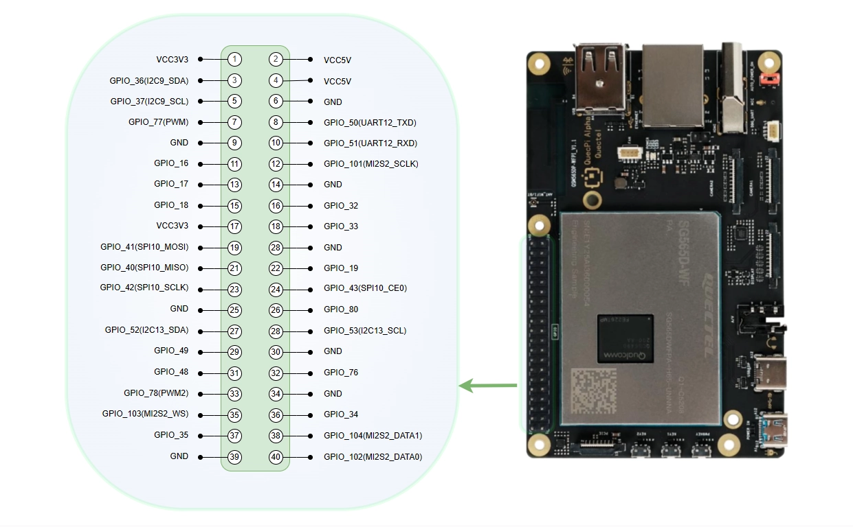
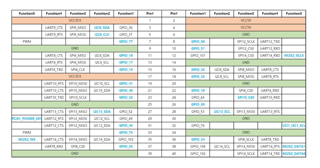
Interface configuration
The configuration file for some low-speed interfaces (i2c9/spi10/uart12_2w/i2c13/spi14) on the 40-pin interface is located at /etc/qpi-config/qpi-config.ini.
Configuration steps:
Modify the
qpi-config.iniconfiguration fileApply the configuration
qpi-config 40pin set
Restart the system for the configuration to take effect
GPIO testing
This section uses pin3 of the 40-pin interface as an example to demonstrate how to use the GPIO function. The gpio_num corresponding to pin3 is 36.
Hardware connection
Connection method 1: Measure voltage with a multimeter
Connect pin3 (GPIO_36) to the positive terminal of the multimeter, and pin6 (GND) to the negative terminal of the multimeter. You can verify if the GPIO function is working correctly by measuring the voltage output of the pin with the multimeter.
Connection method 2: Use the GPIO expansion board indicator lights
You can also connect a Raspberry Pi 4B/3B GPIO terminal expansion board to the 40‑pin expansion interface to test GPIO high/low levels. This expansion board brings out all GPIO pins and is equipped with a corresponding indicator light for each pin. You can configure the target GPIO pin to output mode and connect it to the expansion board. The indicator lights up when the GPIO outputs a high level and turns off when it outputs a low level, allowing you to visually verify if the GPIO level changes are as expected.
For more information about this expansion board, refer to the GPIO terminal expansion board entry in the supported accessories chapter (see: Supported accessories).
Method 1: Control via SHELL commands
The lgpiod service is enabled by default in the system. Execute the following commands in sequence:
Step 1: Open GPIO device
rgs c 999 go 4
Use the go command to open the file /dev/gpiochip4.
Step 2: Set GPIO mode
rgs c 999 gso 0 36
Use the gso command to set gpio 36 to output mode. The 0 in this command is the return value from the previous command, modify it according to the actual situation.
Step 3: Set low level
rgs c 999 gw 0 36 0
Set gpio 36 to low level. At this time, the test pin voltage value is 0V.
Step 4: Set high level
rgs c 999 gw 0 36 1
Set gpio 36 to high level. At this time, the test pin voltage value is 3.3V.
Method 2: Control via Python/C code
If you need to use programming languages to control GPIO, please refer to the following documents:
Python GPIO development - Use the python-periphery library for GPIO development
C/C++ GPIO development - Use the lgpio library for GPIO development
These documents provide complete code examples, compilation methods, and testing steps.
I2C testing
Pin3 and pin5 of the 40-pin interface are the data and clock pins of I2C by default, corresponding to the device node /dev/i2c9.
Tip
If the device node does not appear, you can first use qpi-config mentioned at the beginning of this chapter to configure and enable it.
Test preparation
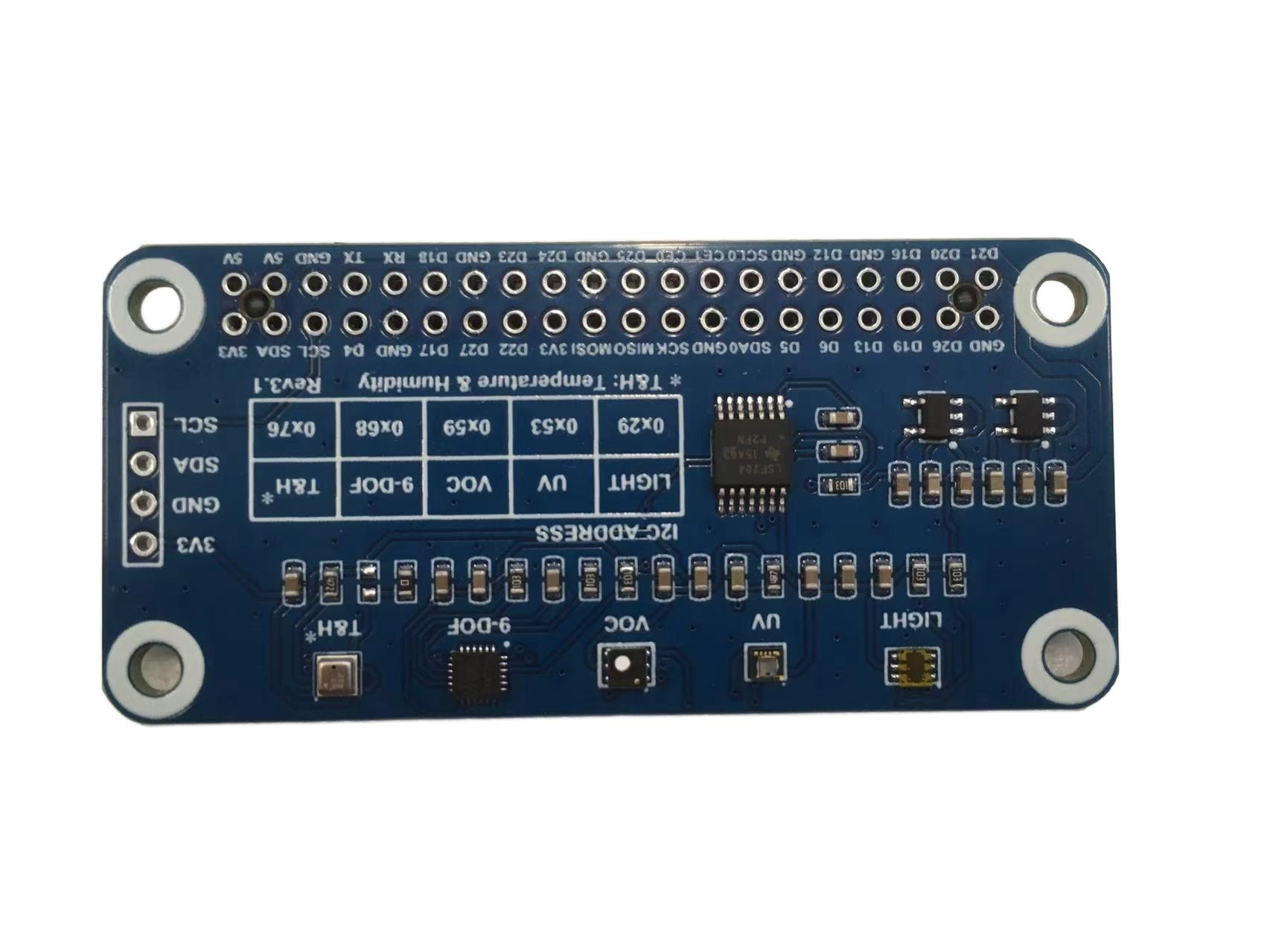
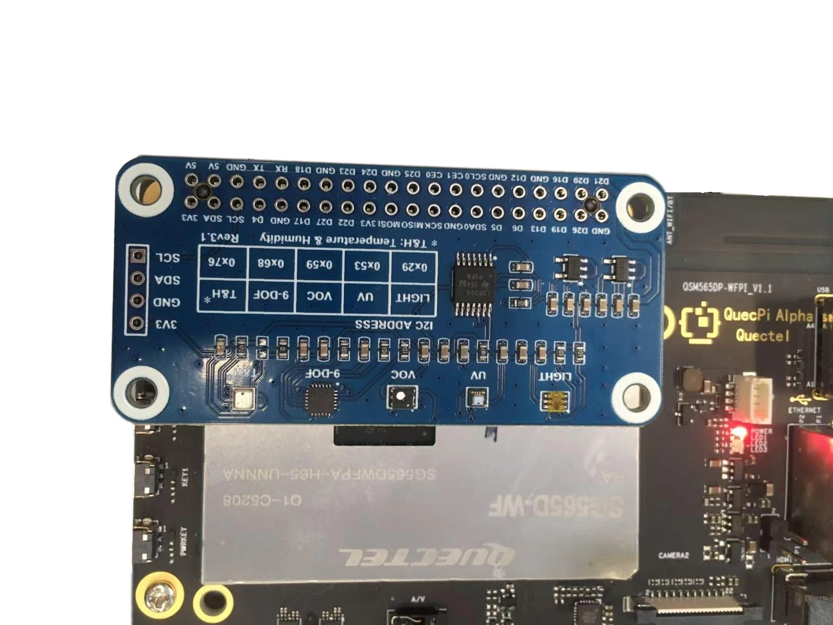
This test uses the Waveshare Environmental Sensor Expansion Board (BME280), connected through the 40-pin interface.
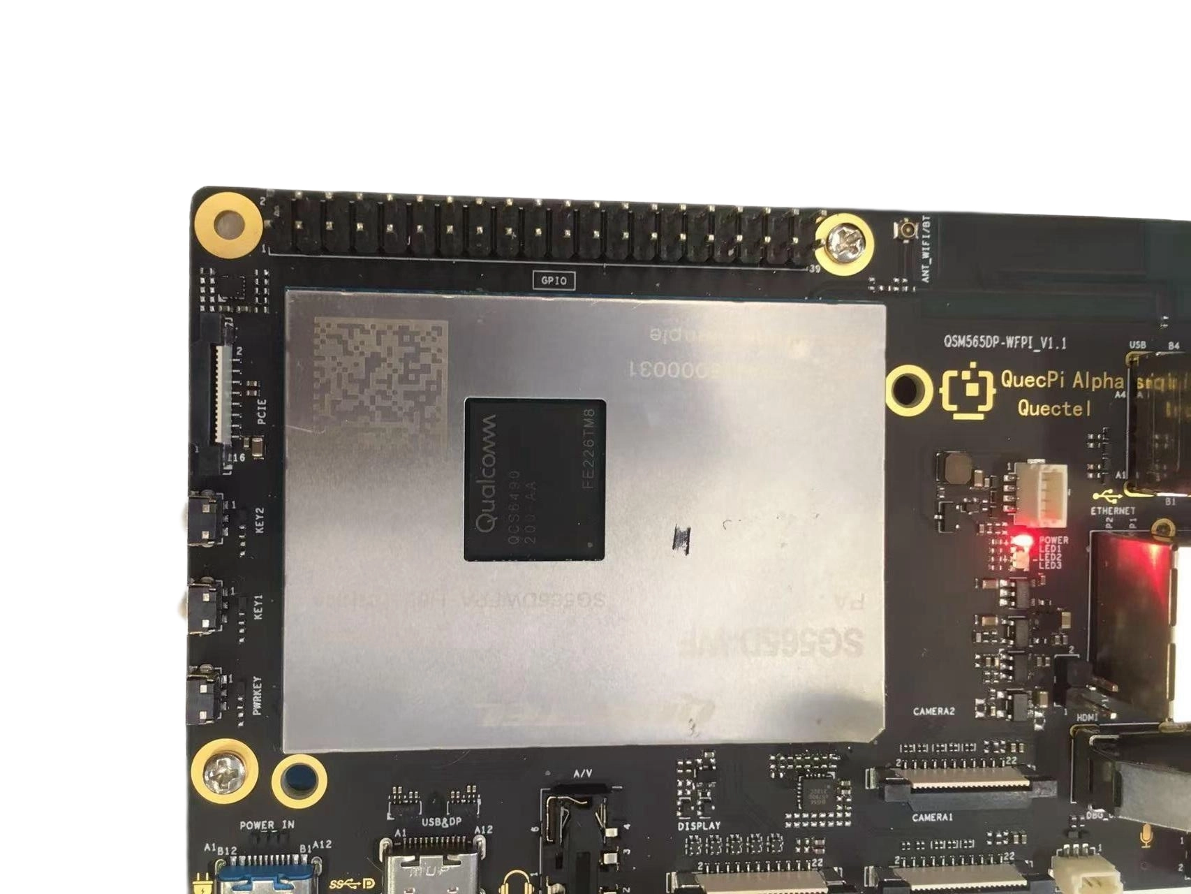
Hardware connection diagram:
Control via C code
Prerequisites
If the lgpio library is not available in the system, please refer to the C/C++ GPIO development document to install the lgpio library.
Step 1: Create source file
Create a new file named envtest.c with the following content:
Click to expand/collapse the full code
Step 2: Compile the program
gcc -o envtest envtest.c -llgpio
Step 3: Run the test
sudo ./envtest
Note
If a “Permission denied” error occurs, you need to run the program with sudo.
After successful execution, the output contains the collected air pressure, temperature, and humidity information:
pressure:    1013.25 hPa
temperature:   25.36 C
humidity:     45.67 %
SPI testing
The SPI function on the 40-pin interface corresponds to the device node /dev/spi10.
Tip
If the device node does not appear, you can first use qpi-config mentioned at the beginning of this chapter to configure and enable it.
SPI loopback testing
This test controls the SPI interface through SHELL commands to verify data transmission and reception functions.
Step 1: Open SPI device
rgs c 999 SPIO 10 0 10000000 0
Use the SPIO command to open /dev/spidev10.0 with a baud rate of 10000000. The command returns a file handle (usually 0).
Step 2: Perform SPI data transmission test
Short data test:
rgs c 999 SPIX 0 1 2 3 4
Long data test:
rgs c 999 SPIX 0 1 2 3 4 0 1 2 3 4 0 1 2 3 4 0 1 2 3 4 0 1 2 3 4 0 1 2 3 4 0 1 2 3 4 0 1 2 3 4 0 1 2 3 4 0 1 2 3 4
Use the SPIX command for SPI data transmission, where 0 is the file handle returned by the previous command, and the following numbers are the data to be sent.
Test results:
When MISO and MOSI are shorted (loopback mode), returns the sent data:
4 1 2 3 4
The first number 4 indicates the number of data bytes received.
When MISO and MOSI are not shorted, returns all 255 (indicating no valid data received):
4 255 255 255 255
UART testing
Pin8 and pin10 of the 40-pin interface are configured as UART function by default, corresponding to the device node /dev/ttyHS2. If the device node does not appear, you can first use qpi-config mentioned at the beginning of this chapter to configure and enable it.
View serial port devices
You can use the following command to view all serial port devices in the system:
ls /dev/tty*
UART loopback testing
This test verifies whether the serial port transmission and reception functions are working properly by shorting pin8 and pin10.
Hardware connection: Short pin8 (TX) and pin10 (RX) of the 40-pin interface.
Prerequisites
The python3-serial library needs to be installed:
apt-get update
apt-get install python3-serial
Step 1: Create test script
Create a new file named uart_loop.py with the following content:
Click to expand/collapse the full code
import serial
import time

def serial_loopback_test(port='/dev/ttyHS2', baudrate=115200, timeout=1):try:# Open serial port
        ser = serial.Serial(
            port=port,
            baudrate=baudrate,
            parity=serial.PARITY_NONE,
            stopbits=serial.STOPBITS_ONE,
            bytesize=serial.EIGHTBITS,
            timeout=timeout
        )if not ser.is_open:print(f"Unable to open serial port {port}")returnprint(f"Serial port {port} opened, starting loopback test (Press Ctrl+C to exit)...")
        test_data = b"Hello, Serial Loopback!"  # Test datawhile True:# Send data
            ser.write(test_data)print(f"Sent: {test_data.decode('utf-8')}")# Read loopback data
            time.sleep(0.1)  # Wait for data reception
            received = ser.read(len(test_data))# Verify resultsif received == test_data:print(f"Received: {received.decode('utf-8')} → Test passed\n")else:print(f"Reception exception: Sent[{len(test_data)}] vs Received[{len(received)}] → Test failed\n")

            time.sleep(1)  # Repeat test every 1 secondexcept serial.SerialException as e:print(f"Serial port error: {e}")except KeyboardInterrupt:print("\nUser interrupted the test")finally:if 'ser' in locals() and ser.is_open:
            ser.close()print(f"Serial port {port} closed")if __name__ == "__main__":# Modify serial port and baud rate according to actual situation
    serial_loopback_test(port='/dev/ttyHS2', baudrate=115200)
Step 2: Run the test
python3 uart_loop.py
Test results:
When pin8 and pin10 are correctly shorted, the program will continuously send data and verify whether the received data is consistent:
Serial port /dev/ttyHS2 opened, starting loopback test (Press Ctrl+C to exit)...
Sent: Hello, Serial Loopback!
Received: Hello, Serial Loopback! → Test passed

Sent: Hello, Serial Loopback!
Received: Hello, Serial Loopback! → Test passed

Sent: Hello, Serial Loopback!
Received: Hello, Serial Loopback! → Test passed
Press Ctrl+C to exit the test program.
PWM testing
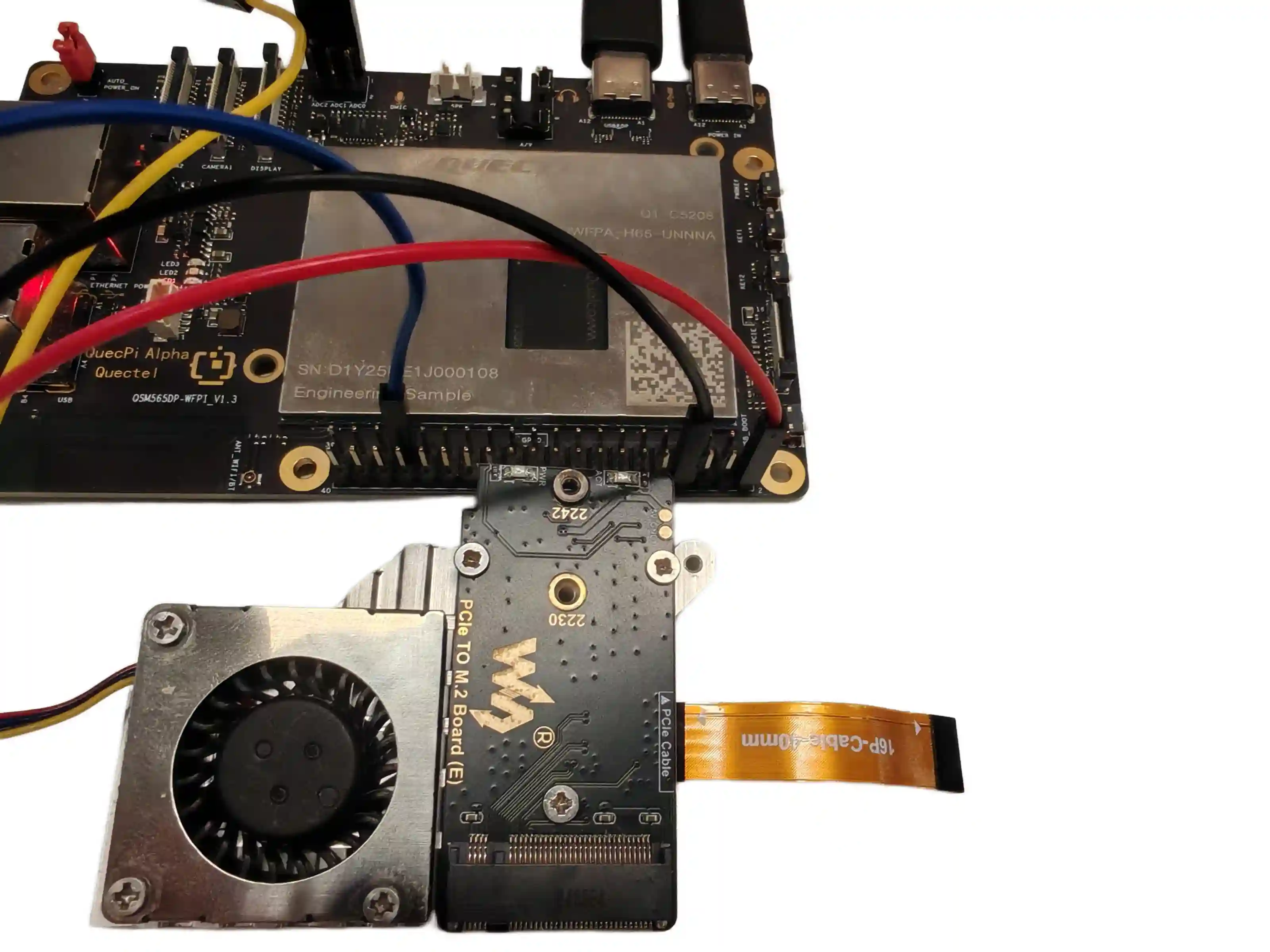
Pin33 of the 40-pin interface is configured as PWM function by default. Here, we choose Waveshare’s 4pin PWM protocol adjustable speed fan as the test device.
Hardware connection
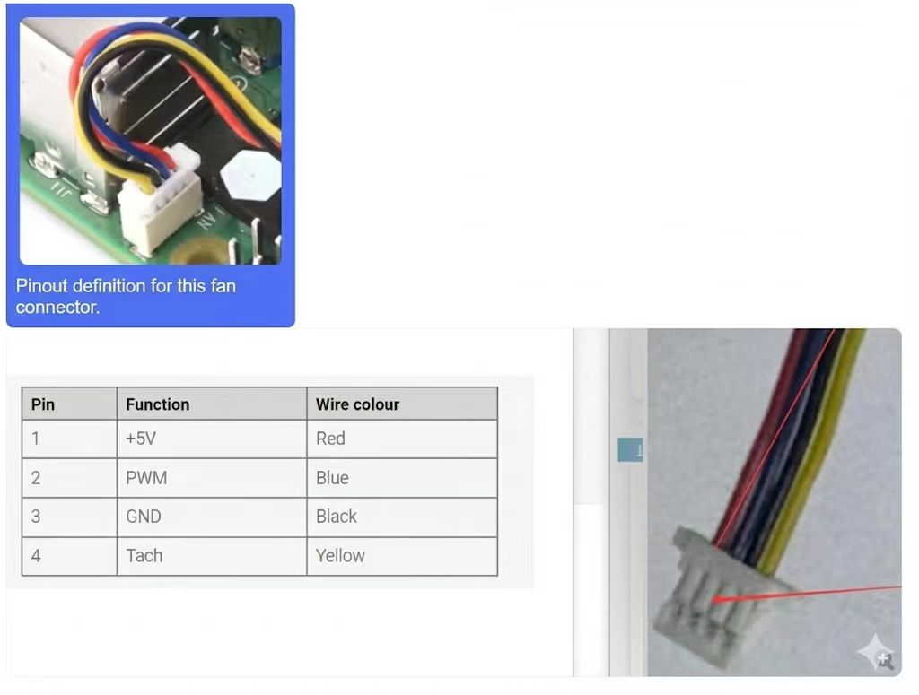
PWM fan wiring definition:
Pin |
Function |
Wire colour |
40-Pin connection |
|---|---|---|---|
1 |
+5V |
Red |
pin2 or pin4 (5V) |
2 |
PWM |
Blue |
pin33 (GPIO_78) |
3 |
GND |
Black |
pin6/9/14/20/25/30/34/39 (any GND) |
4 |
Tach |
Yellow |
pin32 (GPIO_76) |
Connection diagram:
Note
The Tach pin is used to read fan speed and is an optional connection
If you don’t need to read speed information, the Tach pin can be left unconnected
Control via C code
Create a pwm.c file with the following content:
#include <stdio.h>#include <lgpio.h>int main(int argc, char **argv){int h;int gpio = 78;
      float pwmFrequency = 1000;float pwmDutyCycle = 50;

      h = lgGpiochipOpen(4);  // Open /dev/gpiochip4 deviceif (h < 0) {printf("ERROR: %s (%d)\n", lguErrorText(h), h);
          return 1;}

      int e = lgGpioClaimOutput(h, 0, gpio, 0);
      if (e < 0) {printf("ERROR: %s (%d)\n", lguErrorText(e), e);
          return 1;}

      e = lgTxPwm(h, gpio, pwmFrequency, pwmDutyCycle, 0, 0);
      if (e < 0) {printf("ERROR: %s (%d)\n", lguErrorText(e), e);
          return 1;}

      lguSleep(5);lgGpioFree(h, gpio);lgGpiochipClose(h);return 0;}
Compile:
gcc pwm.c -o pwm -llgpio
Execute:
sudo ./pwm
The fan will run at medium speed. You can modify the
pwmDutyCyclevalue in the code (range 0-100) to adjust the fan speed.